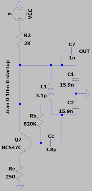
The Colpitts oscillator is represented as a tank circuit composed of an inductor and two capacitors, with the capacitors connected in series.
In this case, an NPN transistor is used to maintain the oscillation of the tank circuit.
ATTENTION: Run simulattion with: Start external DC Supply Voltages at 0V.
See schematic at bottom of page.
Here you can compute the components for a Colpitts Oscillator tank circuit by simply entering the values of the terms referenced below.
ATTENTION: To ensure Oscillation ocours make Ic ≤ Itank.
Obtaining the values to substitute into the circuit shown at the end of the page.
| VCC | Voltage in volts |
| Ic | Collector current in amper |
| Itank | Tank current in amper |
| f | Frequency in hertz |
| Hfe | Transistor gain |
| Ztank | Output impedance in ohms |
| VCC | |
| Ic | |
| Itank | |
| f | |
| Hfe | |
| Rc | |
| Re | |
| Rb | |
| L1 | |
| C1,C2 | |
| Cc | |
| Ztank | |
| ---| Cientific Notation |--- | ||||
| femto | pico | nano | micro | mili |
| e-15 | e-12 | e-9 | e-6 | e-3 |
| Kilo | Mega | Giga | Tera | Peta |
| e+3 | e+6 | e+9 | e+12 | e+15 |
References:
Wikipedia